


Introduction
This document will provide instructions to install the Gimbel Automation Instant Solenoid Kit. Air line connections instructions should be the same across all manufacturers of machines, but the electrical connection will differ for each manufacturer. See the corresponding section for your manufacturer for electrical connections.
Air Line Installation
- Step 1: The solenoid kit has magnets on the side of the unit. These can be used to attach it to the side of your machine where the wires of the kit can reach inside your electrical cabinet.
- Step 2: Input air lines are connected to the back of the unit using the push to connect fittings. There is an input for each solenoid.

- Step 3: The output lines are attached to the front of the unit. The pair of lines will run to your desired device. In the case of a bypass gripper or gripper on a part flipper, the A(NORMALLY FLOWS) hole needs to be plugged.

Electrical Connection for Haas Machines
- Step 1: To connect the solenoid kit to a Haas Machine you may need to purchase the Gimbel Automation Haas I/O Kit if your machine is missing the needed relays (This is the case with most Haas Machines built after 2019). A board missing relays is located behind a cover and located in the lower left of the electrical cabinet. Missing relays look like this:

- If your board has these relays already populated (either as shown below or permanently soldered on), you won't need the I/O kit. If you do need the I/O Kit, you can purchase it here: https://gimbelautomation.com/products/haas-ngc-i-o-kit-relays-terminal-plugs
Insert the components from our kit so your board looks like the picture below:

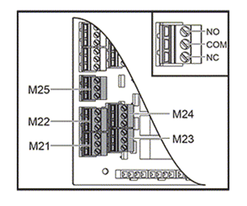
- Step 2:Plug in the phoenix-style connectors that are connected to the wiring of the Instant Solenoid Kit into the I/O board in the area shown in the picture above on the right (green plugs to the left of the blue circle)
💡 Tip: We recommend using M21, M22, and M25 relays before the other two, as the M23 and M24 relays are harder to implement on NGC Haas machines that have been updated.
- Step 3: With the air lines connected and the electrical connected you should be able to control your devices via the controls M-codes (M21, M22, etc. depending on where you plugged in the solenoid kit.
Electrical Connection for Most VMC’s
- Step 1: The preceding Haas example has standard output m-code relays and was specific to Haas I/O boards but any machine with standard output m-code relays can be connected.
- Step 2: To do this you would just connect the solenoid pairs to the NO and COM of the relay. So, in the picture below the red wire would be connected to NO of the relay and the black to COM (the wires could be crossed with the same effect as the relay is just a switch).

- Step 3: Your machine may have a different style connector than the Haas, but you would just wire the connector as instructed above.
Electrical Connection for Brother Machines
- Step 1: To connect the solenoid kit to a Brother Machine you will need to purchase the Gimbel Automation Brother I/O Kit (pictured below). This DIN rail can be attached inside the electrical cabinet to any available DIN bosses, or the relays may be removed from the provided DIN rail and attached to an existing DIN rail inside the electrical cabinet.


- Step 2: Next the signal wires (4 signal and 1 ground boxed in blue below) need to be connected to the Brother I/O board. This may vary depending on the year and model of your machine, so double check with your Brother representative or reference your machine’s manual.

- Step 3: In this example, the green block (color may be different on different years) contains the output signals (100-115) that can be mapped to M-codes in the machine control. The 4 signal wires can be connected to any of the 15 ports that are available. Take note of what device is connected to which solenoid, is connected to which relay, is connected to which signal port. The number of the port will be mapped to an M-code in the control. The green ground wire can be connected to any port in the black block.

- Step 4: On the control, on the external output signal page the ports may be mapped to available M-codes. Reference the manual for your machine to see what M-codes are available and how to access the output mapping page on your control. The picture below is an example of a new control and may look different on your machine depending on the year and model.

- Step 5: With the air lines connected, the electrical connected and the M-codes mapped on your control you should be able to control your devices via the controls M-codes.
Purchase Your Instant Solenoid Kit
Explore AI Summary


