


Table of Contents
Introduction
Spindle Grippers are the easiest way to automate your CNC Machine Tending needs, but there isn't a lot of information out there on how to set them up. This article is specifically to guide you through setting up your Through Spindle Air (TSA) Spindle Gripper.
Note: Through Spindle Air (TSA) is the same thing as Through Air Blast (TAB). We use the term Through Spindle Air in this article.
Getting the Gripper in the Holder
Step 1: Find Your gripper alignment
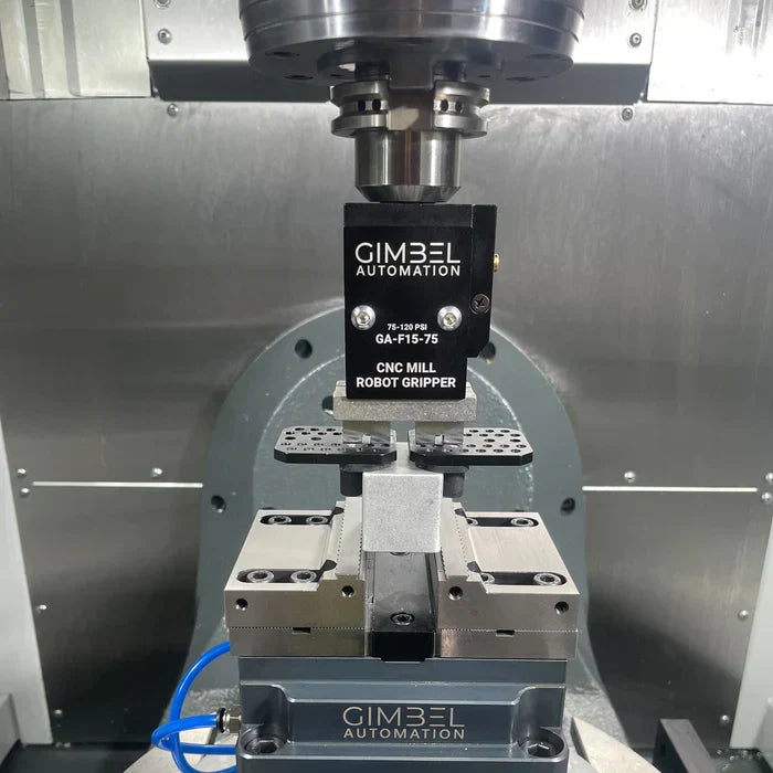
The first step to getting set up is getting your Spindle Gripper ready and properly mounted in a holder, and you need to know how to properly mount it.
🔄 Tool-Holder Orientation:
Your Holder should always be mounted such that the gripper is Faceplate is facing the operator when at the zero position of the spindle. For an Umbrella-Style Tool-Changer, this will result in the drive dogs aligned in the X-Axis (perpendicular to the Gripper Faceplate). For a Side-Mount changer, this will result in the Faceplate and the drive-dogs being aligned.
Umbrella Tool-Changer:
- Alignment: In an Umbrella Tool-Changer, align the Drive-Dogs parallel to the Gripper Face
- Note: These instructions are not for the Bypass Models of Grippers, which have slightly more complicated setup process.

Side-Mount Tool-Changer:
- Alignment: In an Umbrella Tool-Changer, align the Drive-Dogs perpendicular to the Gripper Face
- HSK & Specialty Holder: For Side-Mount HSK Spindles, set the Spindle to M19 P0 and install with the Gripper Faceplate directly facing the operator.

Step 2: Tightening the gripper in the holder
Due to design requirements and to make the Gripper as universal as possible, the 3/4” precision shaft is relatively short. Because of this, only two types of tool holders should be used — either Side-Mount or Hydraulic. If sourcing your own Side-Mount holder, holders that use two smaller set screws instead of one larger set screw usually work better.
🚫 For the TSA Gripper specifically, you should not use an ER Collet holder, even if you have Through-Coolant rated collets. The sealing, even on Through Coolant collets, is not sufficient to allow sufficient operation.
Steps to Tightening the Holder
- Step 1: Mount the Gripper Plates onto the Gripper (do not mount fingers or anything else)
- Step 2: Put Gripper on a sturdy surface standing vertically (resting on its Gripper Plates)
- Step 3: Ensure the 3/4” Shaft has the O-ring at its base to aid in sealing
- Step 4: Slide the Tool Holder onto the 3/4” Shaft
- Step 5: Rotate the Tool Holder to the Correct Alignment for your ATC style
- Step 6: While firmly pressing downward on the Tool Holder to compress the O-ring tighten the Set Screws for your Side-Mount or Hydraulic Holder

Step 3: Indicate In and Relalign
Depending on your application, it usually makes sense to use the Spindle Orient (M19) function of your machine and then indicate in the Gripper such that it is perfectly parallel to the X-Axis of movement.
Understanding the Parts of the Gripper
The Vented Screw
We designed the TSA Spindle Gripper to work with the widest possible range of machines, and some machines have some inherent limits in how they handle Through Spindle Air (TSA), also known as Through Air Blast (TAB).
While this is not the case for most machines, Haas machines specifically tend to have trapped pressure that resides in the Spindle even after Through Air is disabled. Haas and some other brands also use a non-relief Through Air Solenoid, making matters worse.
Because of this, your TSA Gripper is intentionally set up with a single vented M4 Bolt. This M4 Bolt intentionally allows a small amount of leakage, which enables your Gripper to close with virtually any machine.

The Gripper Fingers
Our Spindle Grippers are the only ones on the market that come with a pre-built and adjustable system that lets you grip onto a wide variety of parts. This design is based around these Gripper Plates that have numerous #10-24 tapped holes spaced in a regular pattern.
🚫 WARNING: The Gripper Plates are NOT Symmetrical left-to-right! For micro-adjustment, the plates can be flipped around in order to change the precise closing distance. If you think that your Gripper is gripping off-center, it is very likely that you have one Gripper Plate mounted backwards. Proper mounting should involve the Gripper Plates equally spaced and in mirror configuration on the Gripper Fingers. The shown configuration is INCORRECT. Note how the Left Plate is offset closer to the center and the Right Plate is offset away from center.

Setting Up the Gripper Plates with Fingers
The Gripper Plates are ideal for holding the following:
- Round Stock
- Rectilinear (Rectangular/Square) Stock
- Oval-Shaped Stock
The Opening Width on the standard jaws can be adjusted to hold parts up to 4.125” in size.

Setting Tool Height Offsets
Setting Gripper Height Offset for Macro Programming (Advanced)
- For Advanced Users, we recommend using our Macro Programming to generate your programs. This will require you set a new tool height offset for your gripper only in the event you change out the Gripper finger for a custom 3D Printed or Custom-Machined Gripper Soft Jaw.
- When setting the tool height offset using this method, use your OTS probe or similar to pickup the face that will actually contact the top of the stock or part. If using our Gripper Plates, then you should probe the Rubber Compression Pad.
Setting Gripper Height Offset for Program Generator (Beginner)
- For Beginner Users, we recommend starting out by probing the Gripper with the stock clamped in the Gripper, making programming much more foolproof.
- When setting the tool height offset using this method, either use the Override Pendant on your Instant Solenoid Kit (if using it) to clamp the block before probing tool height, or use an clamp closing the Gripper Plates together as shown below.
Programming your spindle gripper
Macro-Generated Program:
- Less Probing: You only have to probe your Gripper length once, as tool height doesn't change.
- More Capable: The Macro-Generated System allows full two-operation cycling automatically with our Two-Op Module.
- More Customizable: Unlike our online Program Generator, you can alter the actual running template very easily.

- Easiest to Start: Simply plug your program into the Program Generator for machining a single part, give it the correct information, and go.
- Least Likely to Crash: Crashing using this method is very difficult, as this method is not dependent on stock size.
- Requires More Probing: You have to probe every time you change the Z-stock height or part setup, which is more work in the long-run.

Explore AI Summary


