


Introduction
The MCodeAir Kit is the fastest and easiest way to add two pneumatic solenoids to your CNC Machine in order to add both M-code and manually-controlled air outputs to your CNC Machine for automation purposes. In this article, we are going to guide you how to do so using the MCodeAir Kit and the 24V Adapter, available at GimbelAutomation.com
First, you will need the following products:
- https://gimbelautomation.com/products/cnc-instant-solenoid-kit-2-solenoids
- https://gimbelautomation.com/products/24v-solenoid-kit-adapter-for-cobots-and-brother-mills
Note that since the MCodeAir Kit is designed for relay based CNC machines and that the DN or Doosan machines all have 24V outputs, you will need to purchase the 24V Solenoid Kit adapter to get the system working.
Locating the Boards & Connecting the 24V Kit
The DN or Doosan machines are generally controlled by Fanuc controllers; this guide will specifically be for Doosan/DN machines that are using a Fanuc control. The first board that you will need to locate is the terminal board UNDER the main boards in your electrical cabinet. Be sure to always fully power down the machine and the breakers before working on CNC machine electrical.
This is the first board that you will need to locate:

The four spots with the red marks, M91F, M92F, M93F, and M94F are used for the external M-code functions, and are what we are looking for in this guide. These will be the 24V output that your first wire will go in from the 24V Converter Kit for the MCodeAir Solenoid.
The second board you will be looking for is the Ground connection to complete the circuit. This is part of the terminal array generally to left of the board above. The terminals under the “M” section is where we will connect the single GREEN wire for the 24V Convert Kit.

Then, you will need to connect the 24V Connector Kit as shown by the diagram below. Ensure the colors are matched properly. The coloring of the non-green wires is not strictly limited to below, but changing which colored wire is in which M-Code Control will change which of the relays in the Converter Kit below is controlled by the corresponding M-Code commands.


Properly Configuring the DN/Doosan Control for External M-Codes
At this point, you will want to refer to the MCodeAir Instant Solenoid Kit Manual in addition to this document. In order to get control of all four external M-codes on a Doosan or DN Solutions CNC Machine, the following setting must be configured properly:
In order to set the 4 M-Codes to operate independently, set setting Keep Relay 5.4 to 0.
💡 Tip: In setting up these outputs to operate in this way, the same M-code that turns the output to ON will also turn it OFF. Essentially, the DN control flips the current state of the output based on the present state. So for relay output M91, an M91 command will turn the output ON when it is first received, and then an additional M91 command will turn the output OFF.
Connecting the MCodeAir Instant Solenoid Kit to the 24V Converter
At this point, you will want to refer to the MCodeAir Instant Solenoid Kit Manual in addition to this document:
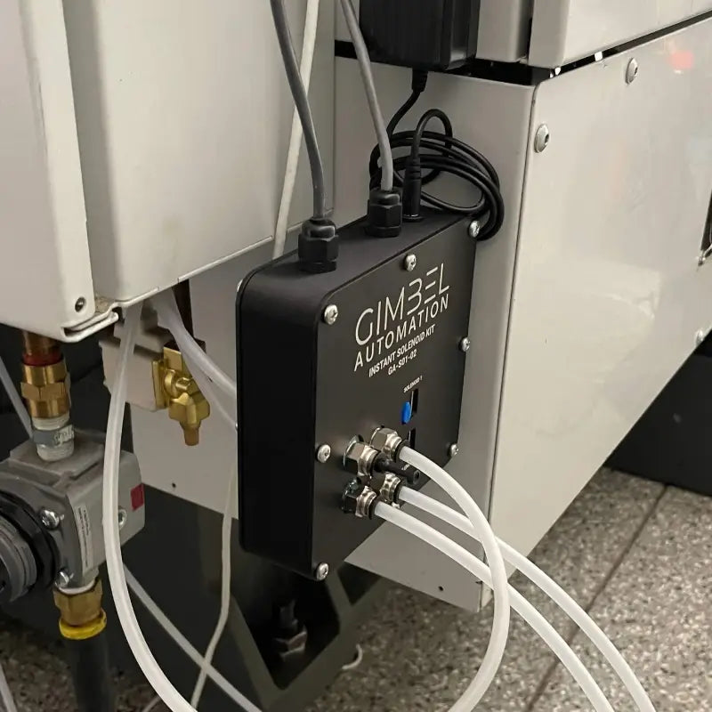
- Step 1: To connect the solenoid kit to a Machine you will need to purchase the Gimbel Automation 24V Converter I/O Kit (pictured below). This DIN rail can be attached inside the electrical cabinet to any available DIN bosses, or the relays may be removed from the provided DIN rail and attached to an existing DIN rail inside the electrical cabinet.


- Step 2: Next the signal wires (4 signal and 1 ground boxed in blue below) need to be connected to the Brother I/O board. This may vary depending on the year and model of your machine, so double check with your Brother representative or reference your machine’s manual.
- Step 3: Refer to the MCodeAir Instant Solenoid Kit manuals on how to use and operate your MCodeAir Kit.
-
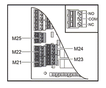
Step 3: With the air lines connected and the electrical connected you should be able to control your devices via the controls M-codes (M21, M22, etc. depending on where you plugged in the solenoid kit.
Electrical Connection for Most VMC’s
- Step 1: The preceding Haas example has standard output m-code relays and was specific to Haas I/O boards but any machine with standard output m-code relays can be connected.
- Step 2: To do this you would just connect the solenoid pairs to the NO and COM of the relay. So, in the picture below the red wire would be connected to NO of the relay and the black to COM (the wires could be crossed with the same effect as the relay is just a switch).

- Step 3: Your machine may have a different style connector than the Haas, but you would just wire the connector as instructed above.
Electrical Connection for Brother Machines
- Step 1: To connect the solenoid kit to a Brother Machine you will need to purchase the Gimbel Automation Brother I/O Kit (pictured below). This DIN rail can be attached inside the electrical cabinet to any available DIN bosses, or the relays may be removed from the provided DIN rail and attached to an existing DIN rail inside the electrical cabinet.


- Step 2: Next the signal wires (4 signal and 1 ground boxed in blue below) need to be connected to the Brother I/O board. This may vary depending on the year and model of your machine, so double check with your Brother representative or reference your machine’s manual.

- Step 3: In this example, the green block (color may be different on different years) contains the output signals (100-115) that can be mapped to M-codes in the machine control. The 4 signal wires can be connected to any of the 15 ports that are available. Take note of what device is connected to which solenoid, is connected to which relay, is connected to which signal port. The number of the port will be mapped to an M-code in the control. The green ground wire can be connected to any port in the black block.

- Step 4: On the control, on the external output signal page the ports may be mapped to available M-codes. Reference the manual for your machine to see what M-codes are available and how to access the output mapping page on your control. The picture below is an example of a new control and may look different on your machine depending on the year and model.

- Step 5: With the air lines connected, the electrical connected and the M-codes mapped on your control you should be able to control your devices via the controls M-codes.
Purchase Your Instant Solenoid Kit
Explore AI Summary